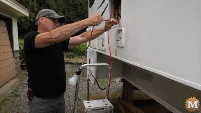
Plugging in the RV to shore power
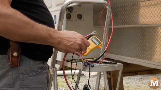
I’m ready to turn on shore power and see if the converter will charge these batteries.
When they’re fully charged this battery monitor coming from the shunt should read accurately.
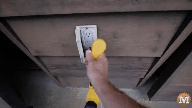

I’ll plug into shore power and then we’ll go see if the converter is charging the battery.
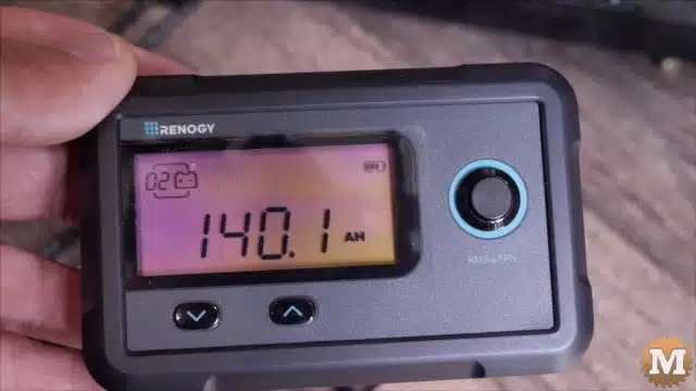
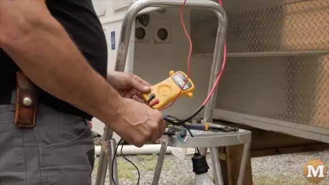
There’s a little battery indicator in the top right hand corner and it’s indicating that the battery is charging. While that’s charging I wanted to say I’m not a licensed electrician or a solar installer — I’m just a DIY’er like most people on YouTube trying to learn what I can and put together my own systems.
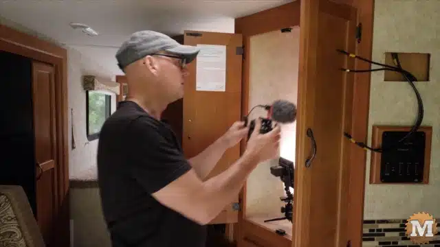
Wiring for the transfer switch
While the battery is charging, and everything seems to be working really well, I’ve added some wiring ahead of time for the transfer switch. And I’ll get into that in more detail when I install that but, now I’m going to put the solar panels on the roof. Then install the charge controller and fuses.
Charge Controller and Solar Disconnect Box
This morning I got my solar charge controller and disconnect box installed in the closet.
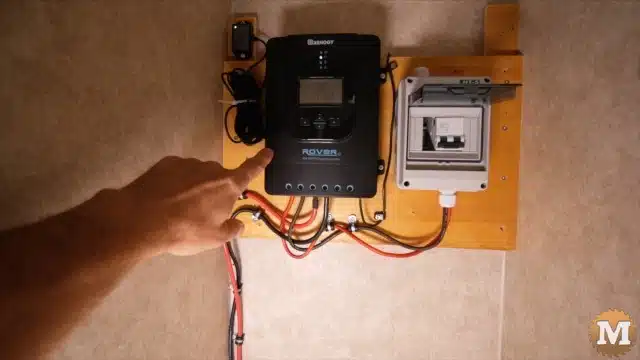
And this solar charge controller has a Bluetooth module that can connect to my cell phone. There’s a disconnect for the solar panels and the wire will connect to it once I get the panels on the roof. That wire will come in through the top and then out into the “PV” positive and negative on the charge controller.
(Disclaimer: As an Amazon Associate I earn from qualifying purchases. Thank you for helping to support my content this way. )

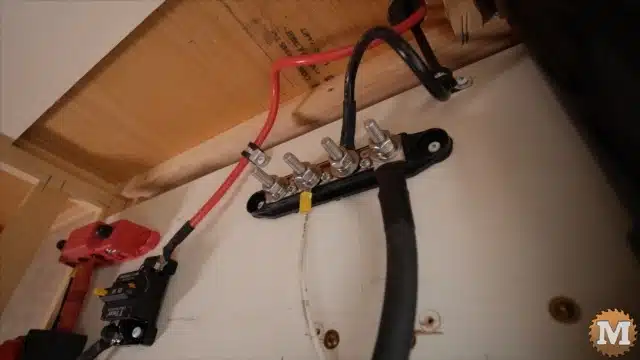
Then out the “Battery” wires which go down to the battery compartment below. Then those black and red wires (the positive and negative from the output from the solar charge controller) come through the floor. The black connects to the negative bus bar and then the positive comes over to this 50 amp fuse and that is wired down directly to the positive terminal of the battery.
Installing the inverter
I’m now ready to install the inverter. I have it mounted in this space on this one side wall and I have a ground wire from the terminal to the frame of the camper.
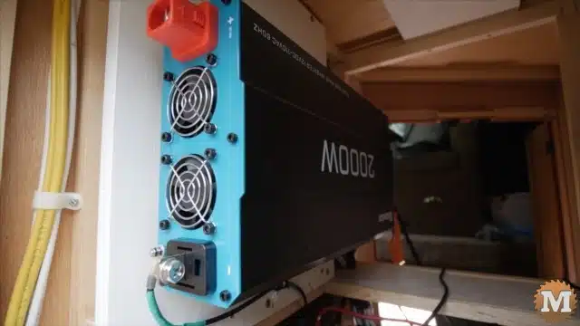
I have my inverter almost ready to connect but, before I connect the positive wire to the positive terminal, I’m going to have a spark.
Recharge the inverter capacitors
There’s capacitors in the inverter that need to be pre-charged so, I’ve set it up with a light bulb that I’m going to connect in the line to slow down the surge of current that goes to the capacitors as they load.
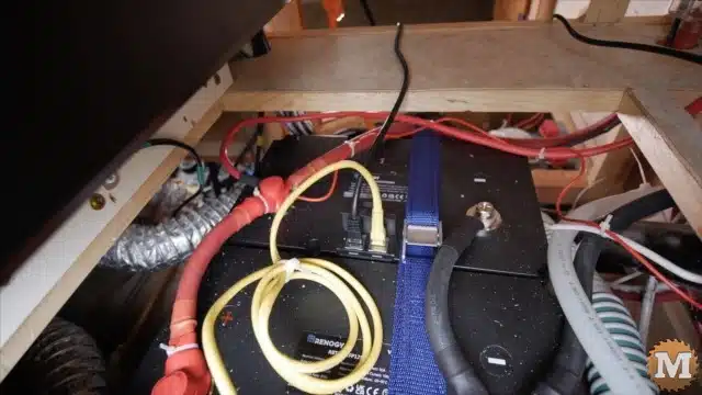
I’ve got my negative terminal on the bus bar and it’s on the same bolt that comes directly from the negative terminal on the battery. And that’s coming around and secured to the negative terminal on the inverter.
Then on the positive side I have the positive wire connected to the bus bar also on the same bolt. It’s going to come around and follow that and go into the positive terminal.
But, like I say, I need to pre-load this first. Let’s give this a try.
And after several attempts I could not get the bulb to light up like I thought it would.
Finally I’ll try a lower wattage bulb — something like an LED — and we’ll see what happens with that. And again it did not work.
But, the voltage is climbing slowly. I still think maybe there’s just too much resistance even with that little bulb but, I don’t have any other resistors to try so I’ll probably just let this run for a while and see what happens.
My experiments here were a flop
So, I’ve had this connected for around an hour now and it’s gone from about half a volt up to almost 10.6 volts. So, obviously this is too big a resistor. But, since it’s been running for an hour now some of the capacitors have the load already.
I think when I make my connection there shouldn’t be as much of a spark to load it the rest of the way.
And there was no spark at all when I made the connection. So I’ll go ahead and put this red wire in place and the inverter will be connected.