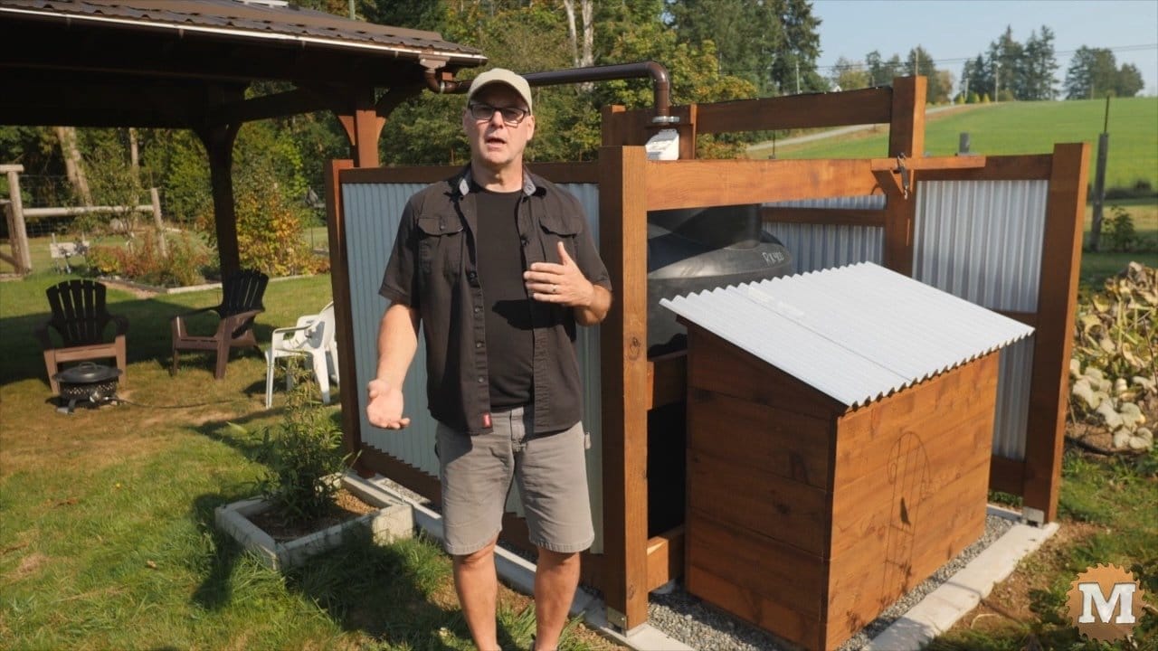
In this 4th episode of my off grid rainwater system series I’ll install a solar panel on the roof of our garden pavilion behind me.
Then wire that to a controller that charges a deep cycle battery. And that will power a 12 volt water pump to irrigate part of our garden. I’m not a solar panel installer or electrician, just a DIY’er that’s enthusiastic about solar.
Around 5 years ago I installed a solar system on our RV. And that system is working flawlessly to this day. That was a lot of fun to do so I was looking forward to building another system here in the garden.
Jump to:
Off-Grid Rain Tank Part 1 – Pour the Tank Foundation
Off-Grid Rain Tank Part 2 – Build the Tank Surround
Off-Grid Rain Tank Part 3 – Tank Plumbing and Fittings
Off-Grid Rain Tank Part 4 – Install a Solar Powered Pump
See the Youtube Video Part 1 or Part 2 or Part 3 or Part 4
(this is a transcript from the video)
Off Grid Rainwater Harvesting System – PART 4: solar panel and pump
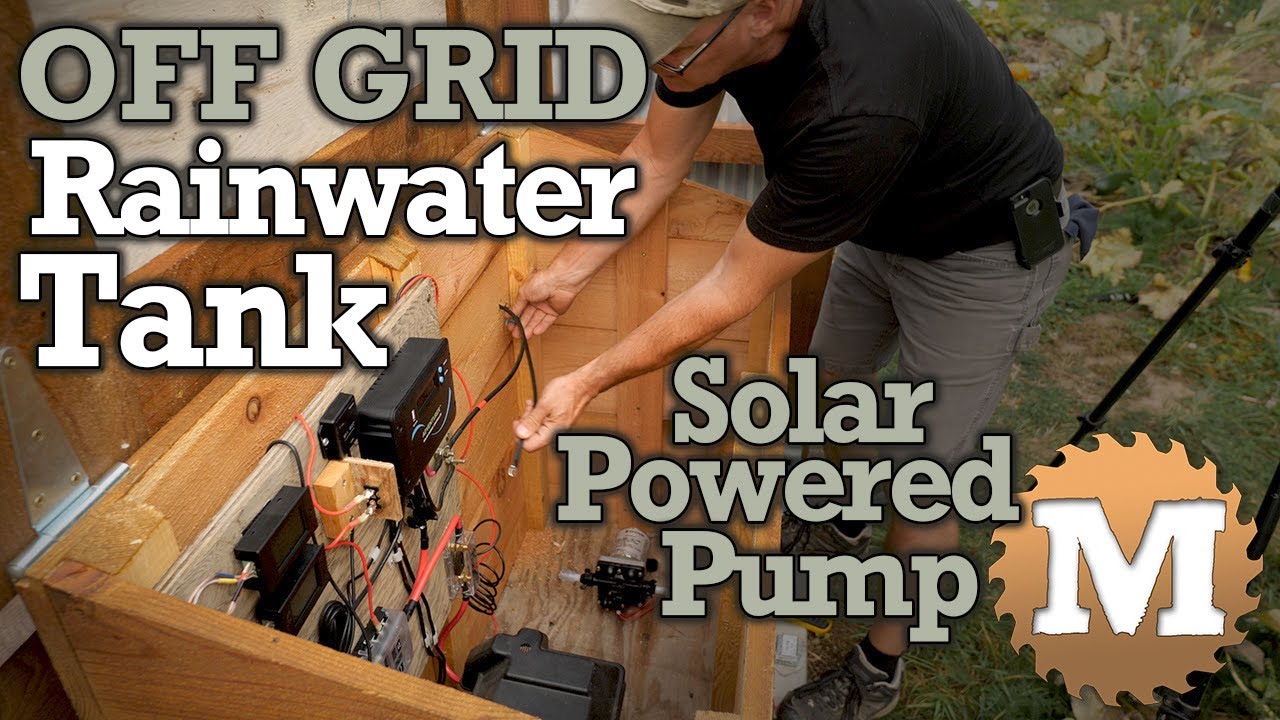
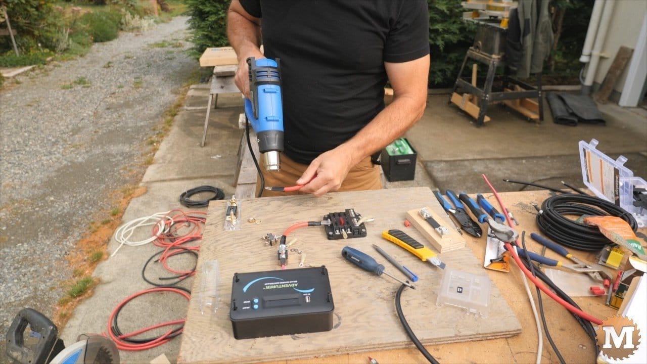
The solar controller and other electrical parts will be first mounted on a piece of 3/4″ plywood. Then this will be attached to the back wall of the mini pump house box. The solar controller must be connected to a battery first before it can be connected to a panel. So this is why I’ll build the control board first. I bought a 100 watt panel and controller kit from Renogy. I have a similar setup on my RV and everything is still working fine. I think this is my favorite part of installing this rainwater harvesting system, the solar board.
(Disclaimer: As an Amazon Associate I earn from qualifying purchases. Thank you for helping to support my content this way. )
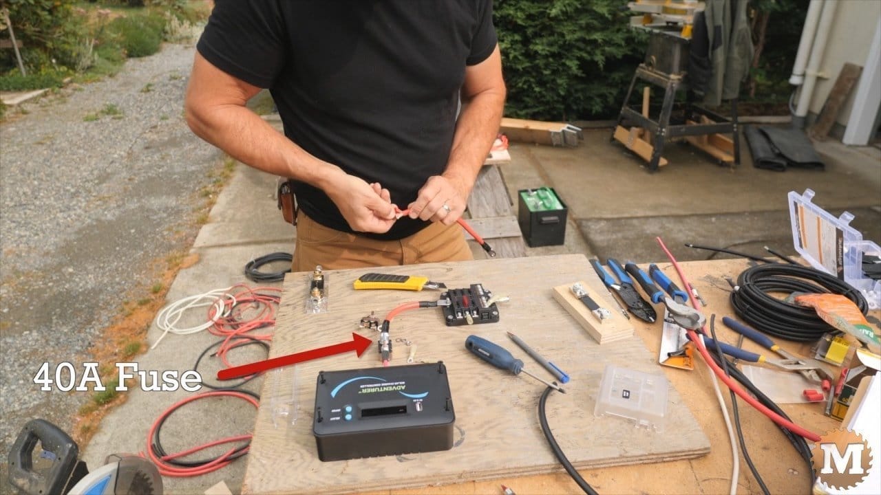
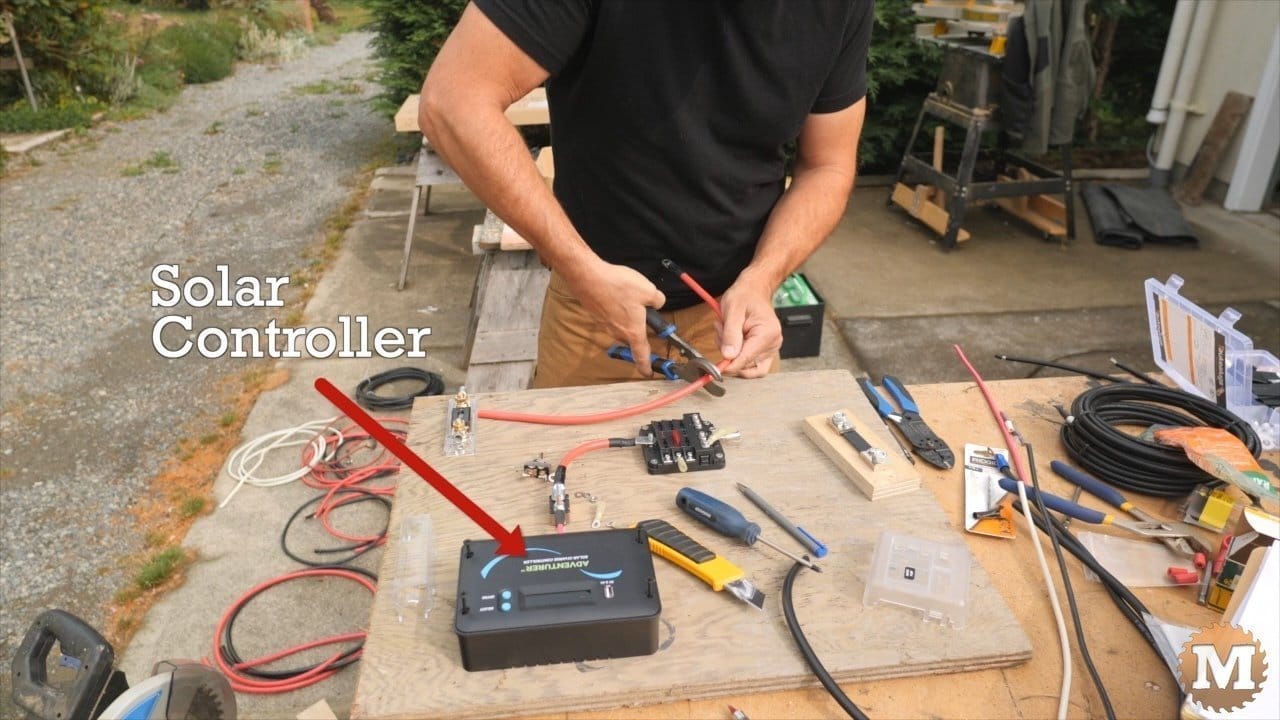
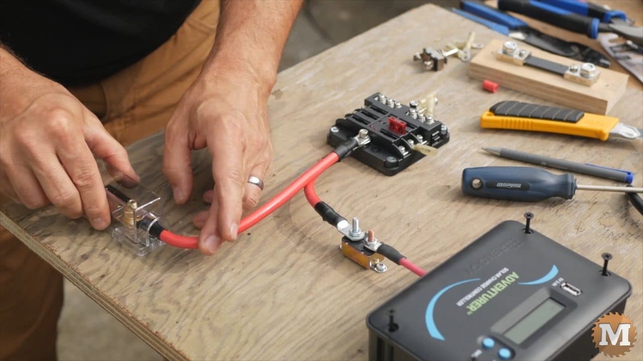
I first mounted the controller. Then a fuse block in pretty much the middle of the board.
From the controller to the fuse block is a red positive wire that has a 40 amp fuse.
To the left of the fuse block is a ANL fuseholder. I sized the fuse according to the gauge of wire going to the battery and with the option of adding a 750 watt inverter later. Once I have the layout set for where everything goes on the board I attach the components and begin to make up the wires for the connections.
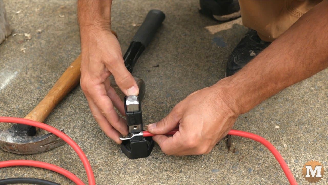
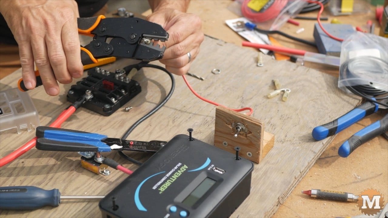
Lug Crimper
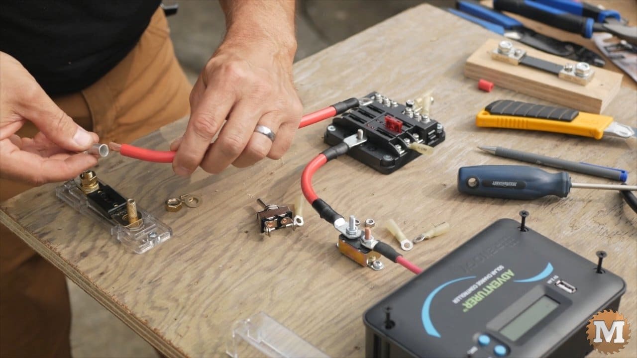
Here I’m cutting and stripping the wire from the positive of the fuse block to one terminal of the ANL fuse. I want to remove just enough insulation so there’s no wire showing when I slide the lug on.
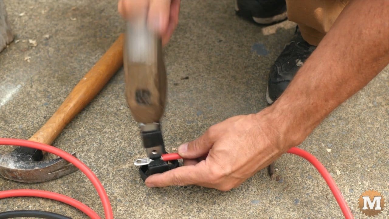
I have a simple lug/cable crimping tool and it works really well. It’s cheap and its fast. This one is spring loaded so I just set the lug in the jaws, hold the wire, then hit it with a hammer.
Heat Shrink Tubing
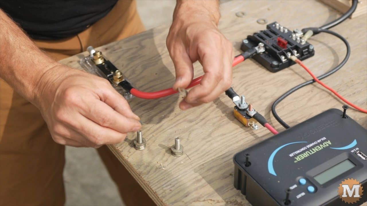
I check the fit then slide on some heat shrink tubing. This will make the connection water tight.
I’ll secure that cable with washers and nuts and check that the cover of the fuse block still fits.

On the other side of the board I’ll add a shunt to the black negative wire that will lead to the battery.
Battery Shunt
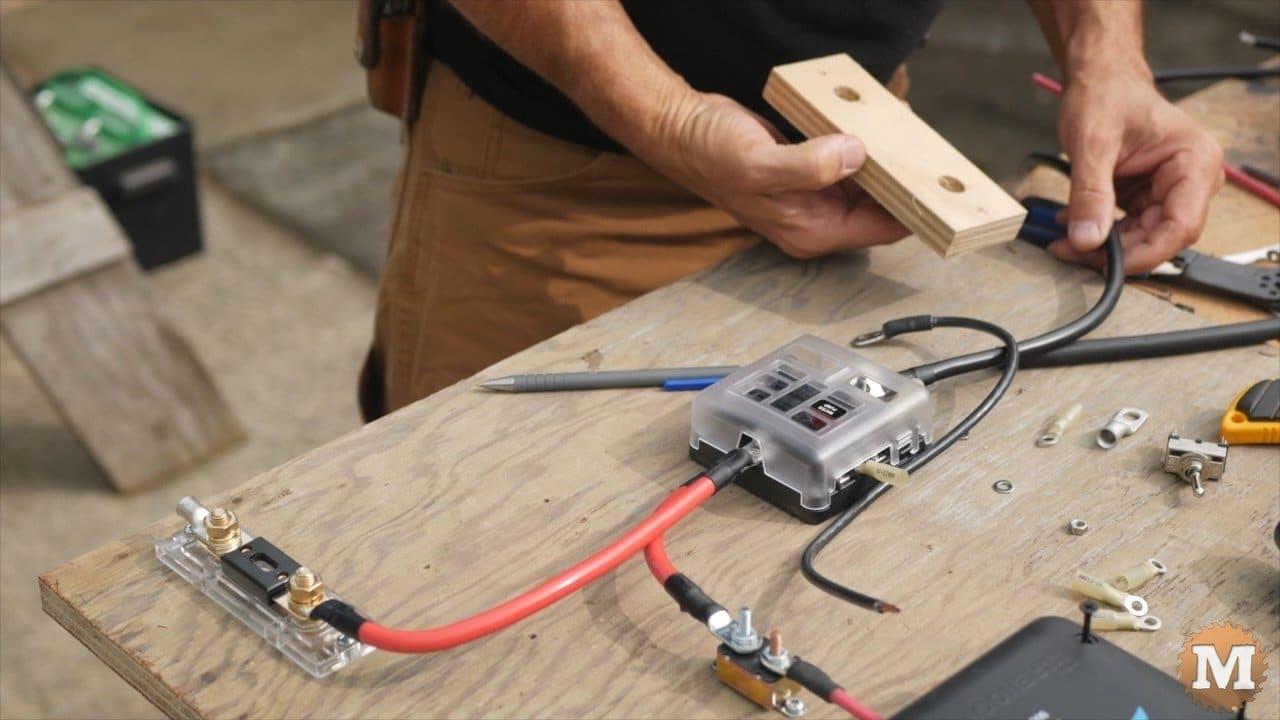
I fabricated a holder for this shunt from scrap plywood as it didn’t come with one. A shunt will allow me to monitor how much power is going in or out of the battery.
I’m now making the negative wire from the controller to the fuse block. And then the negative from that same terminal to the shunt.

The wire from the controller is 8 gauge and the wire to the shunt is 4 gauge.

Here I’ll add a toggle switch for the water pump. I made a small bracket from plywood for this switch. Then I’ll run a positive wire from the switch to the fuse block. This circuit in the panel will have a 10 amp fuse.
I’ll strip that wire then crimp on a connector. Then heat the sleeve to shrink it. Then secure that wire to the block.
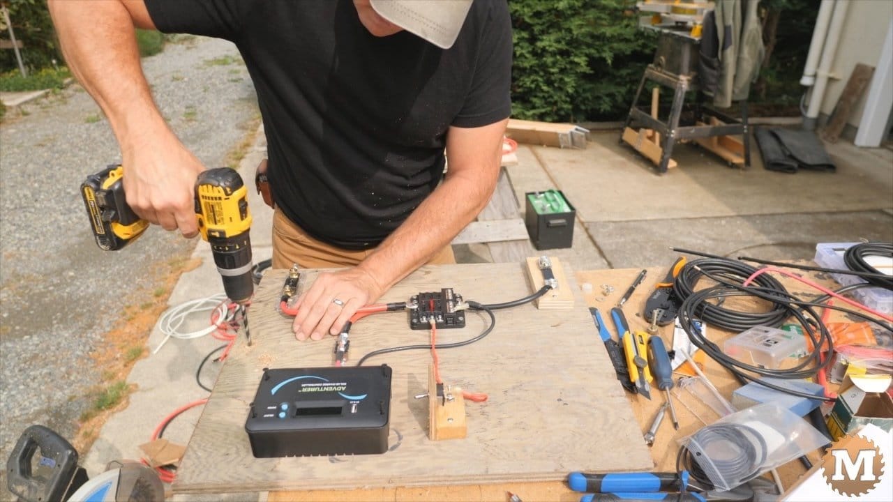
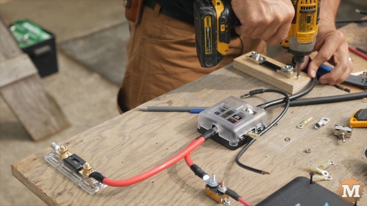
I drill two holes through the plywood. Then add two bolts to make terminals for the solar panel wires. Then I’ll make up the positive and negative wires that go from the controller to these terminals.
DIY Solar Terminals
I’m doing this to make connection and disconnection of the panel wires easier. The controller that came with the kit has terminal screws at the back. And they will be difficult to get to once I mount this board in the pump house box.
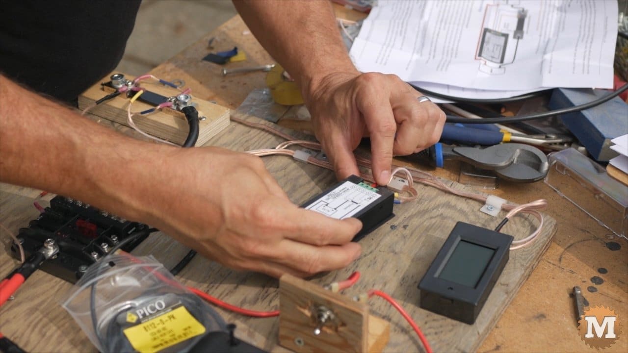
The monitor displays are attached to the shunt and will show the charging and discharging of this battery in this system. I used speaker wire and crimp connectors for this.
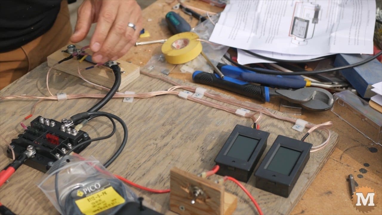
The displays also need power so there’s wires to the panel for this. I’ll attach these monitors to the plywood with velcro.
Smoke Test!!

Now I’ll connect the red positive wire to the battery. Followed by the negative. If everything is wired correctly then the solar controller will show the battery voltage. And one of the monitors will show a small draw from the battery as well.

I’m sure it’s just me but I really like making up these systems and mounting and connecting all the hardware. It gives me a real sense of satisfaction.