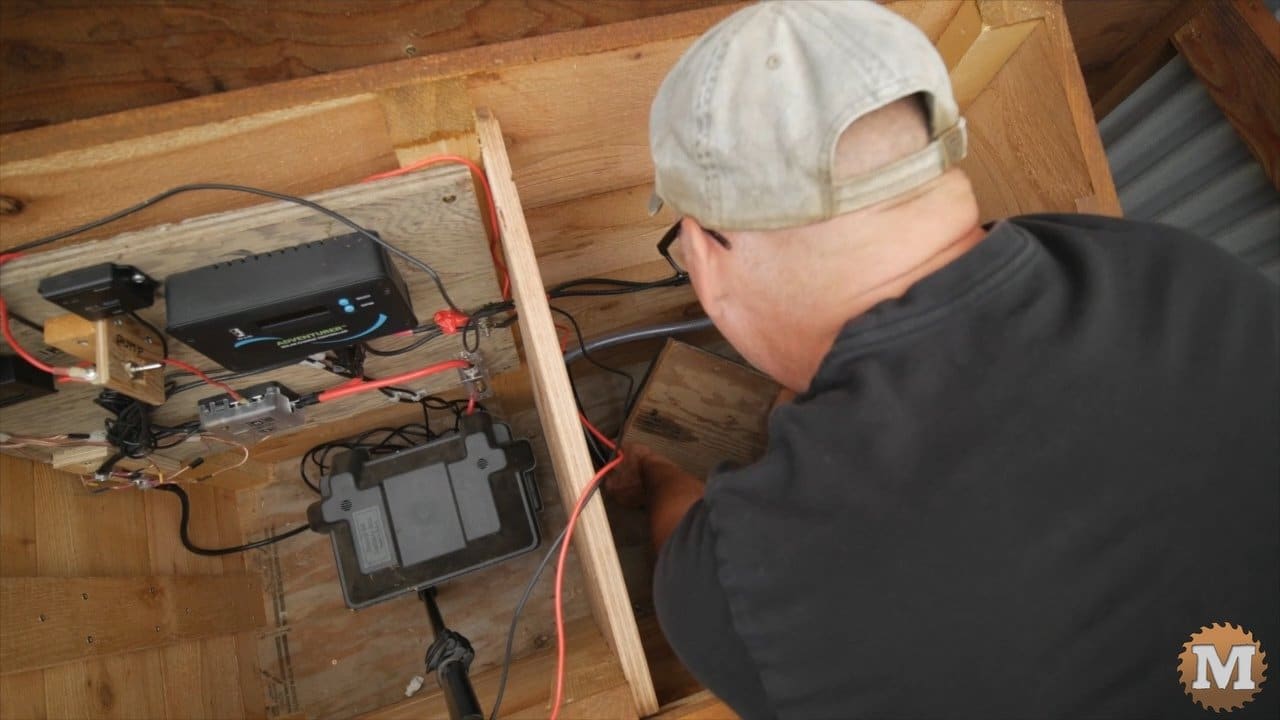
Mount the Board in the Mini Pump House
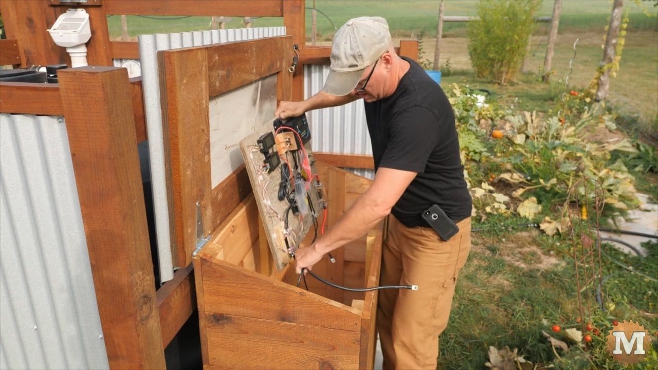
Then I can mount this on the back wall of the box and connect the battery terminals. I designed this rainwater harvesting system with room for expansion.
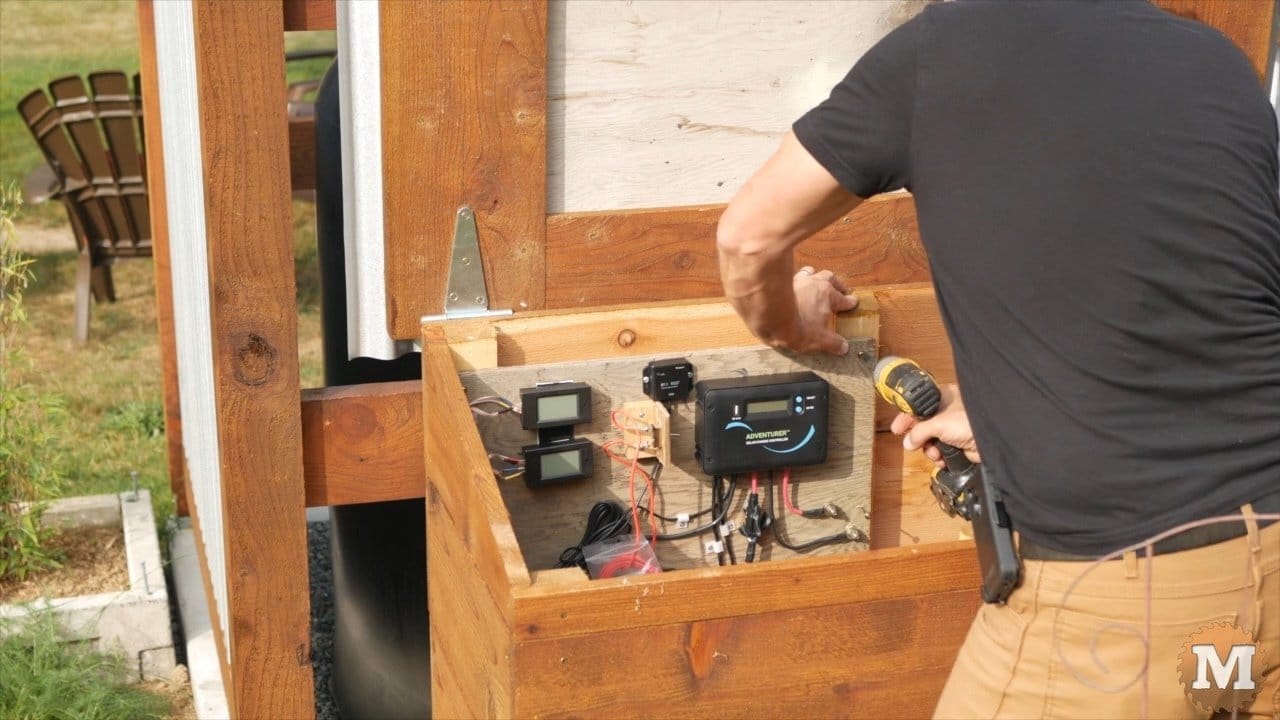
The 12V pump I have won’t draw a lot of amps so for now a single 100 watt solar panel will work for this system. The roof of the pavilion is sloped to the south and the pump will only be used in the summer months when there’s a lot of sun.
The Solar Panel

The kit comes with roof mounting brackets.
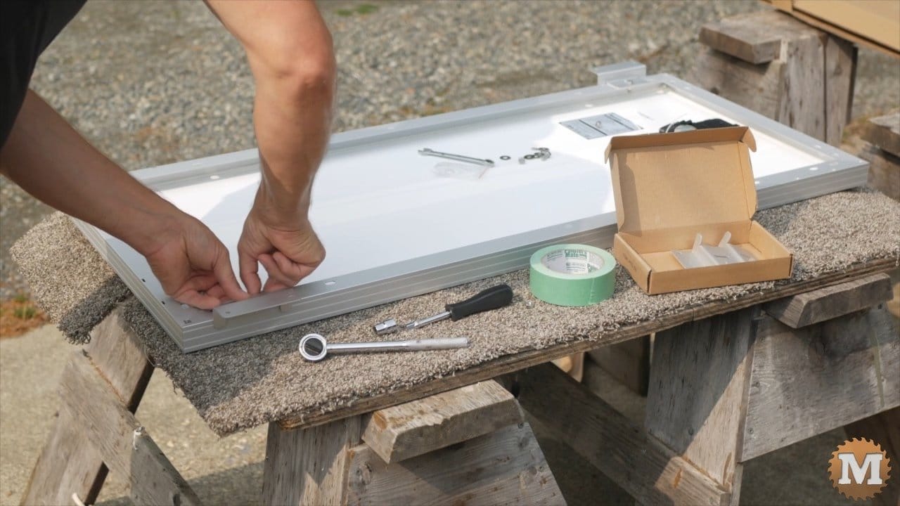
And they are attached to the panel with nuts and bolts.
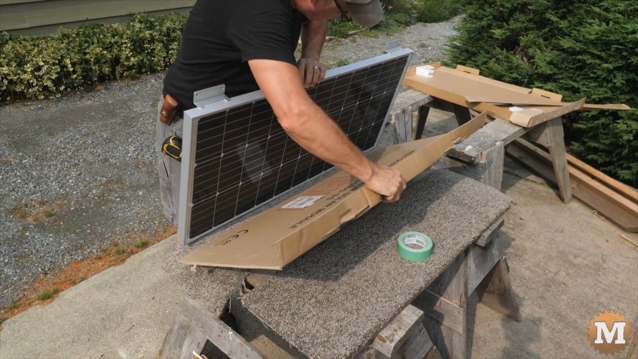
To protect the panel while I’m handling it I’ll cut some cardboard and tape it to the face. And this will also prevent any shorts or sparks from the wires if I accidentally cross them. I’m not sure if I needed to do this. But, it can’t hurt.
Mount the Solar Panel
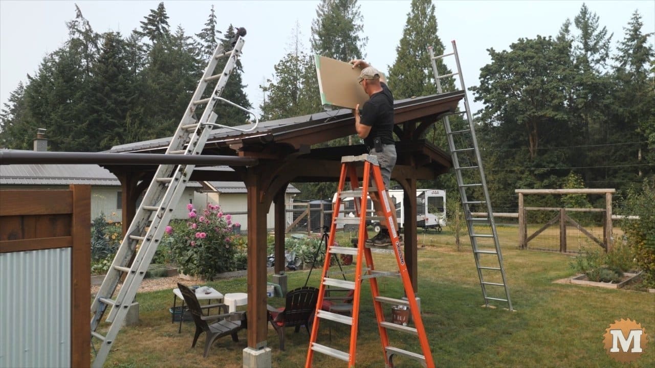
On the roof of the pavilion I’ll set the panel in place and check that the feet of the brackets sit flat between the ribs.
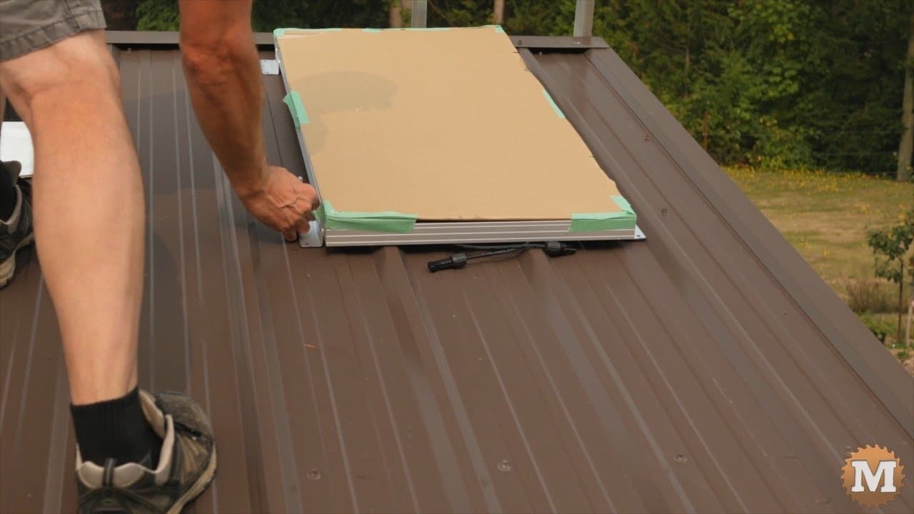
Looks like it just fits.
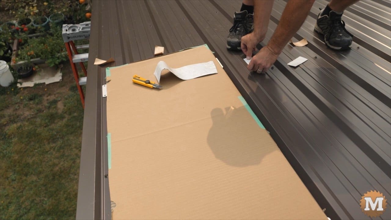
I cut a strip of Eternabond tape and stick it to the roof under the brackets. This should make a water tight seal. And the roofing screws have a rubber washer too.
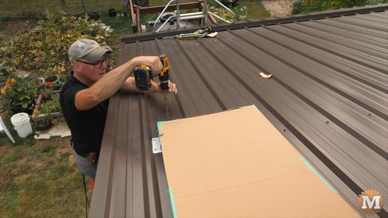
Now I can drill two holes in the roof for the panel wires.
(Disclaimer: As an Amazon Associate I earn from qualifying purchases. Thank you for helping to support my content this way. )
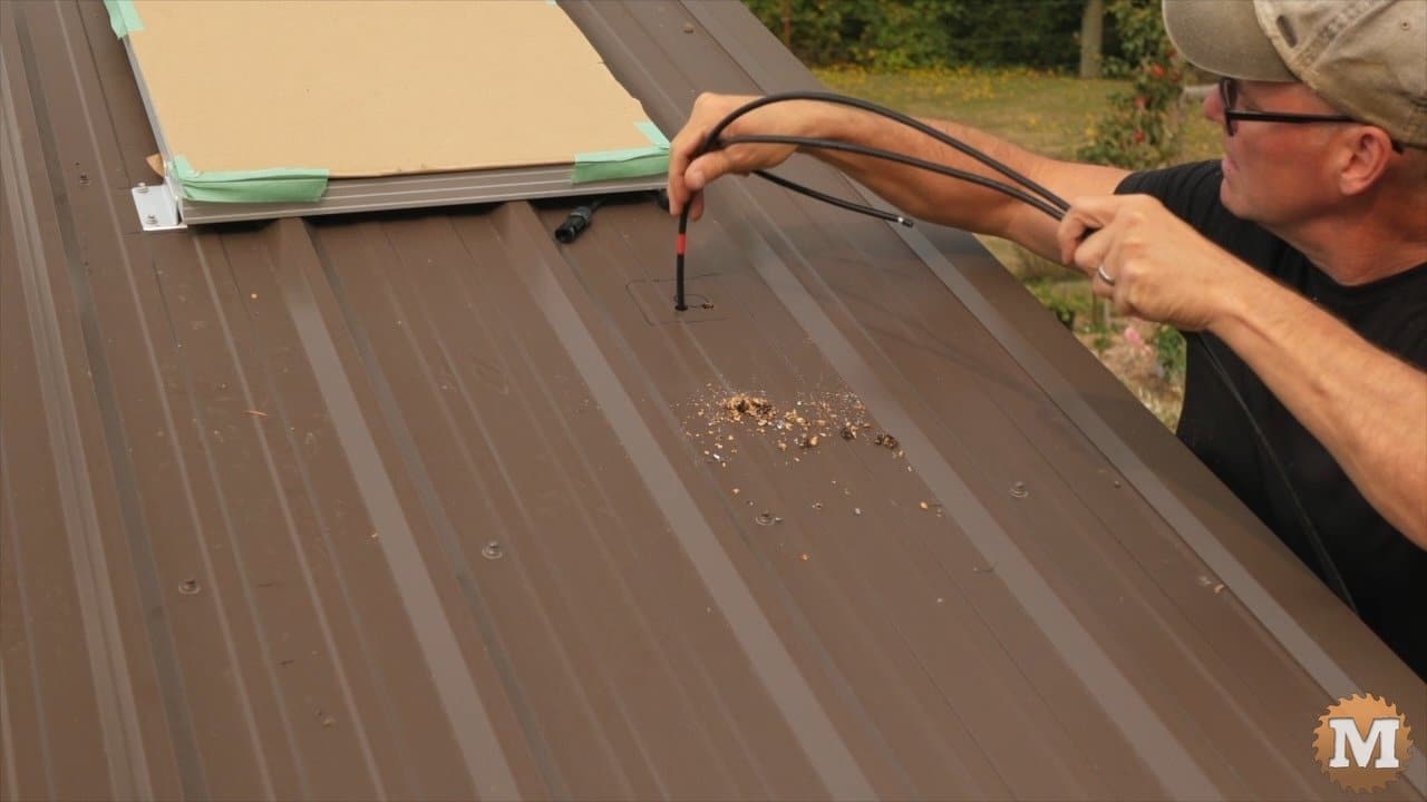

These wires will run through a water tight housing that I’ll silicone to the roof.
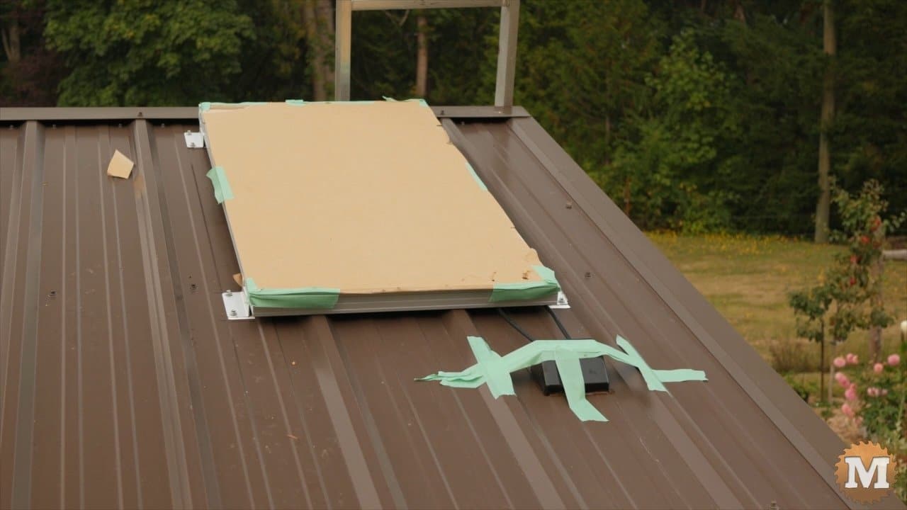
I’ll tape that in place while the silicone cures. Then connect these wires to the panel and tuck the connectors up underneath.
Running Wire to the Pump House
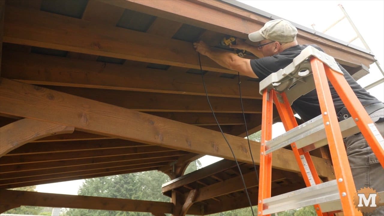
And I can now attach these wires to a rafter with cable ties.
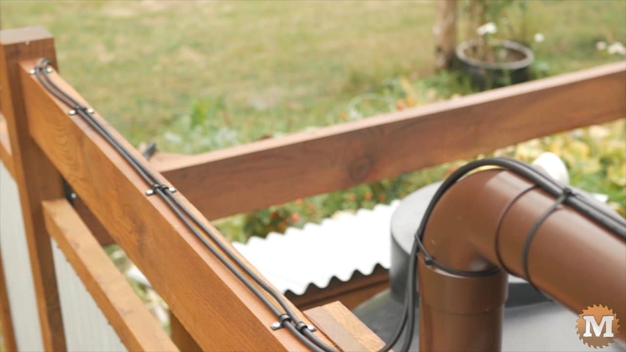
The wires run down the rafters, along the downspout pipe, across the top of the surround and down and behind the pump house box.
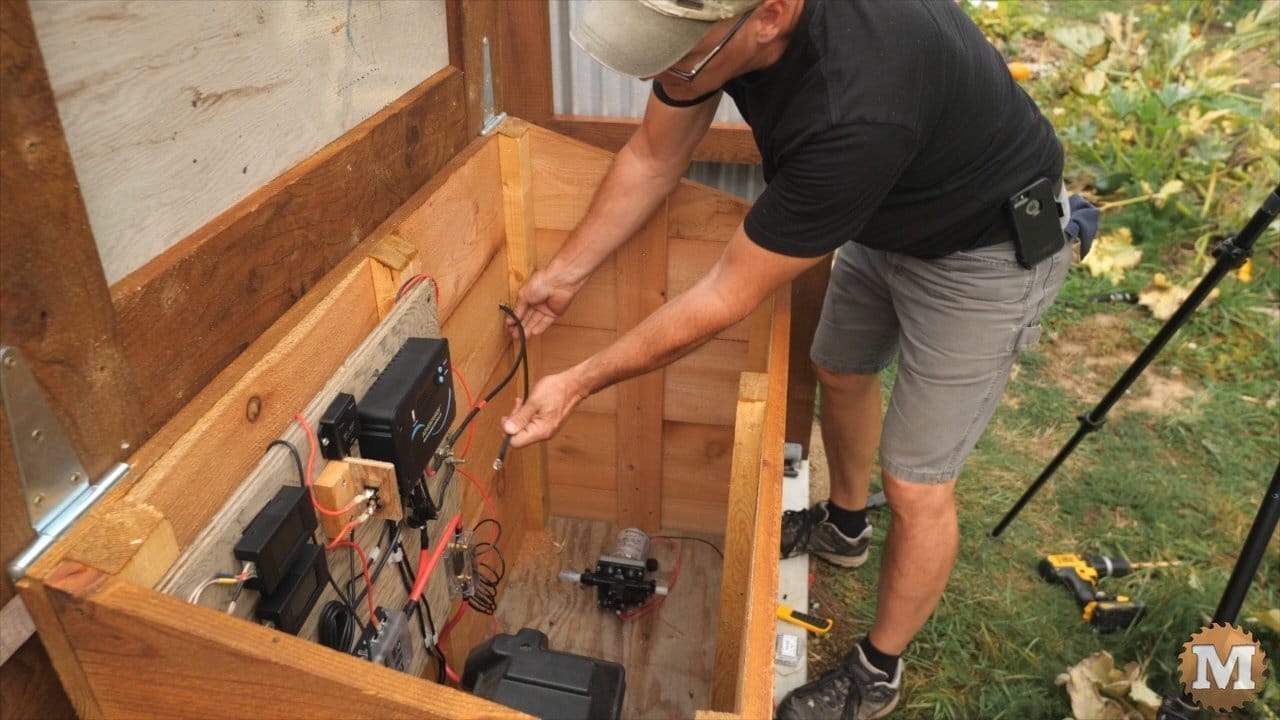
I added lugs to the ends of these wires and then connect them to the bolt terminals on the board. And it worked out that the wires that came with this kit were exactly the right length to just make it to the terminals.
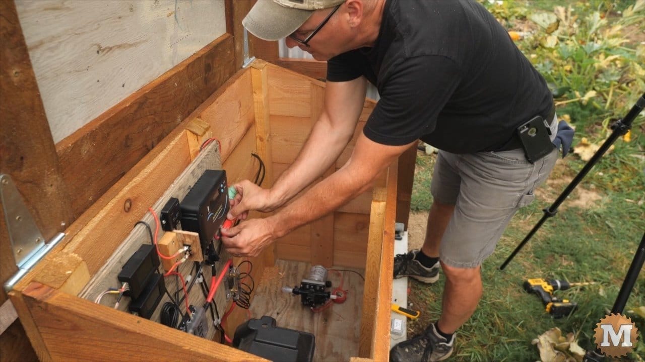
I’ll tape up the bare positive terminal. And now I can remove the cardboard from the panel.
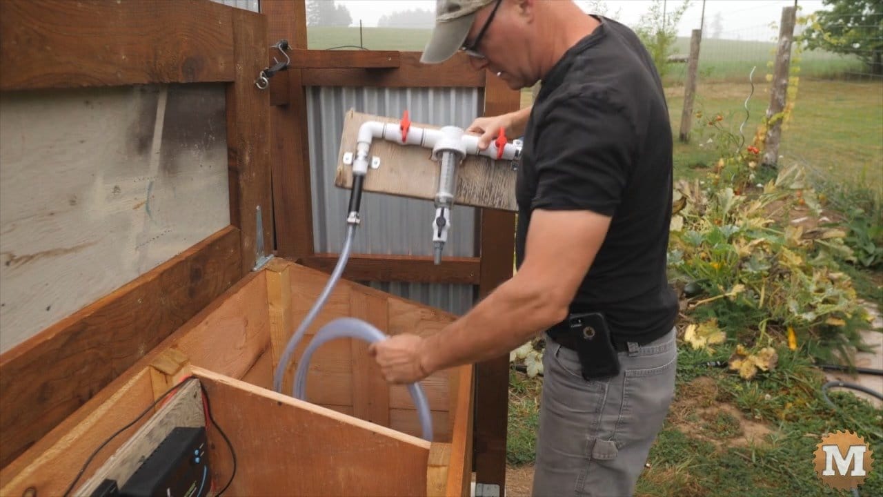
Prepare the Water Filter
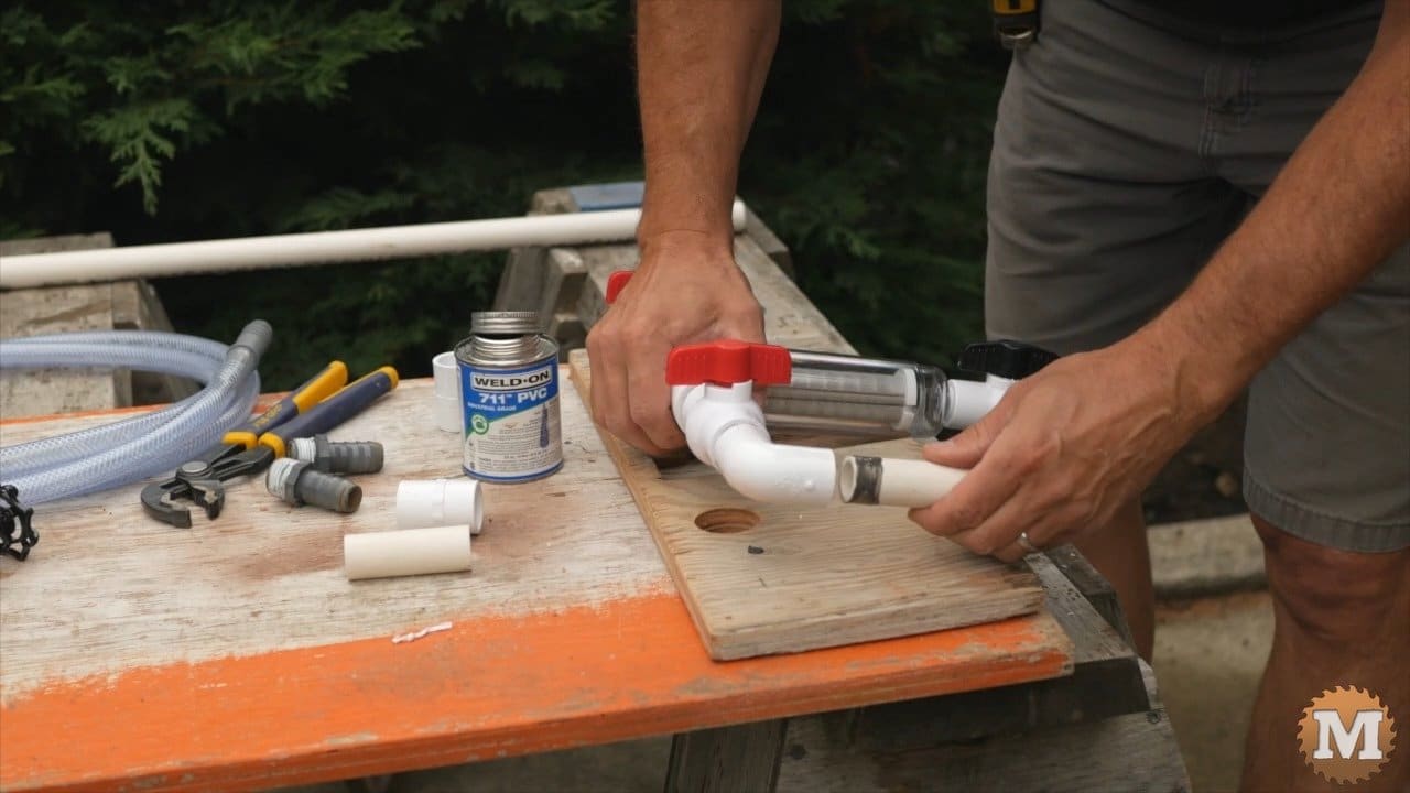
I have a spin down sediment filter that I will also mount on a board before adding it to the pump house. It has 3/4″ ball valve on either side of the filter and I add 90 degree elbows and a barbed hose adapter. The drip irrigation will have additional finer filters but this spin down will catch anything that makes it past the downspout screen.
And I can mount that in place.
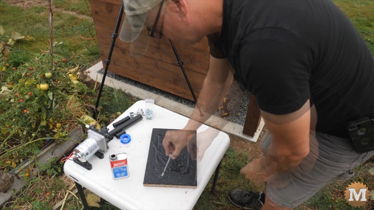
Even though these 12 volt pumps have rubber mounting feet they still vibrate a lot. So I though I would try to reduce this with an additional rubber mount. I cut a piece of plywood and glued on a scrap piece of rubber flooring. Then I’ll glue this to the bottom of the pump house box.
I’ll use contact cement for this. You can also see from this angle that I added a plywood divider to the box. This was to keep the electrical side separate from the potentially wet pump side. In case I had a leak somewhere. I’ll set the pump in place and screw it to this small piece of plywood. The contact cement worked very well and I don’t think this board is ever coming off.
Secure the 12V DC Water Pump
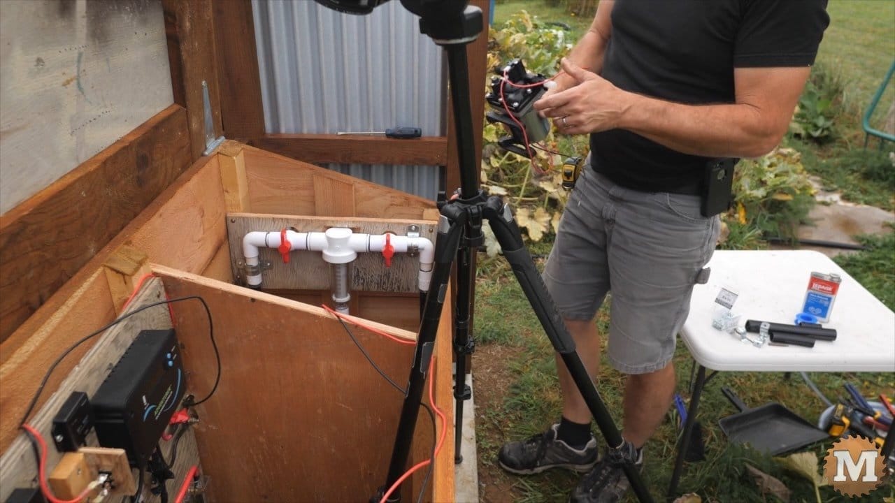
The spin down sediment filter has a valve at the bottom so you can quickly remove some of the debris that builds up. I’ll drill a hole through the box and connect a half inch house for this sediment to drain.
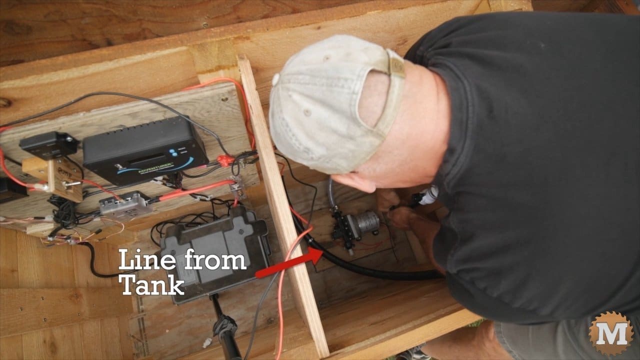
A black 3/4″ water line runs in to the box from the bulkhead float fitting on the tank and is connected to the barbed fitting on the filter assembly.

And the outlet of the filter to the inlet of the pump with a clear braided hose. And another clear hose to the outlet side of the pump.