Timber Frame Gazebo Corner Braces
I made most of the braces for this Timber Frame Gazebo and my Woodshed Project at the same time. If you saw the Woodshed Build Series then you might recognize some of these images. But I’ll quickly go through the steps again for this project.
I made the braces using two by eight red cedar.

I laid out and cut a plywood pattern according to the plans. I trace the pattern then cut opposing forty five degree angles on the miter saw.

This ensures the brace will be ninety degrees.

I cut the curved sections on the band saw.
I sand this cut smooth with a small hobby belt sander.

The flexible sanding belt follows the curve of the brace quite well. The braces will be attached to the posts and beams with a long lag bolt at a twenty degree angle to help pull the brace tightly into the corner.
to the Drill Press
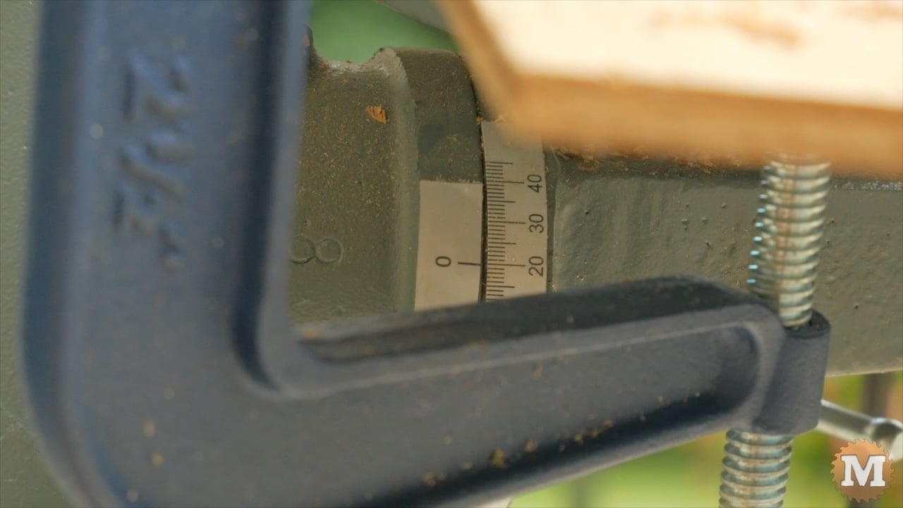
I tilt the table on my drill press to this angle, mark the hole center, and clamp some simple stops to the table to hold the pieces in place.

A countersink with a forstner bit drops the head of the bolt neatly below the surface. Then I switch bits to drill the pilot hole for the shank of the lag bolt.

Using my angle grinder with a sanding disc, I bevel the edges of each corner braces except the edge that mates with a post, girt, or beam. So all the outside edges.

Install Corner Braces
I mark the post and the beam two inches in from the outside edge to guide the brace location. I applied some exterior wood glue then hold it securely in place.
(Disclaimer: As an Amazon Associate I earn from qualifying purchases. Thank you for helping to support my content this way. )

Then drill into the post and beam and drive in a lag bolt with an impact driver. I’ll hand tighten with a socket wrench to prevent thread rip out.

For this structure, I think this simple brace is more than enough to give the frame rigidity. A brace with a proper tenon mortised into the post and the beam is always the best option, but for this build I think a flat mounted brace with a long, angled, lag bolt is sufficient.

On the plans I have included a slightly larger brace for the inside corners as an alternative.
The braces that mate with the girts are installed flush with the outer face of the post, as the girts are the same thickness as the braces.


