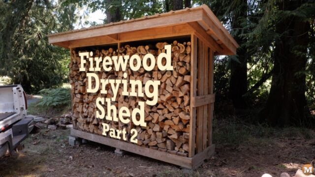
This is the Sketchup Drawing Plan download page for the Firewood Drying Shed shown in my YouTube video.

Download the plan I used: Firewood Drying Shed Plan and Cut List
Background of the Sketchup Drawing Plan
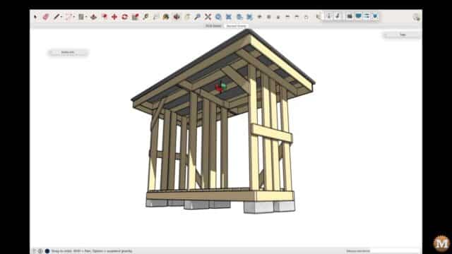
This is Part 2 of my series on designing a simple firewood drying shed. In Part 1 I emptied the shed and moved the wood closer to our house and re-stacked it into our larger timber frame style woodshed. And with the smaller shed emptied I was able to take measurements and come up with a rough sketch on paper. Then take those diagrams and measurements and create a 3D CAD model.
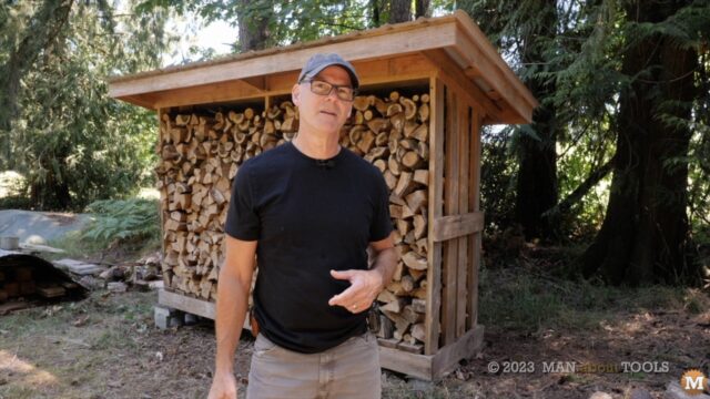
Hi everyone, it’s Kent from Man About Tools, and in this blog post I’m going to show you how I made a drawing from this small woodshed.
If you haven’t seen Part 1 then maybe you will get more out of this blog post if you watch that video first and/or read the blog post.
Create a Fully Dimensioned Drawing & Cut List

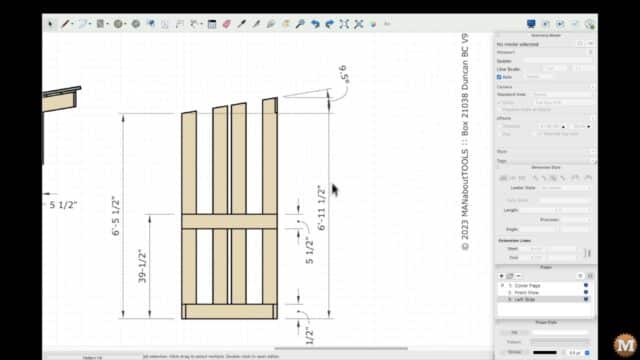
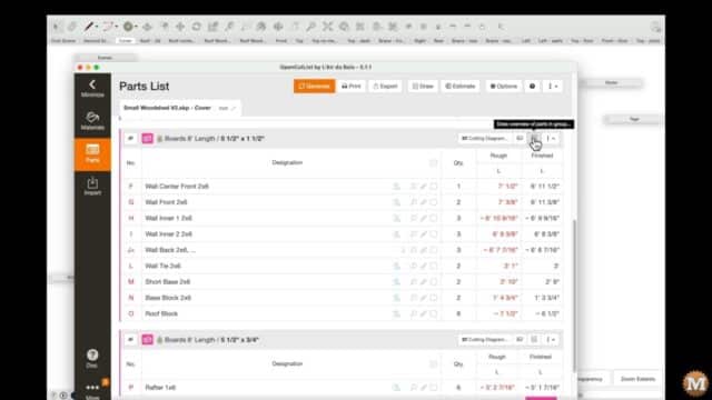
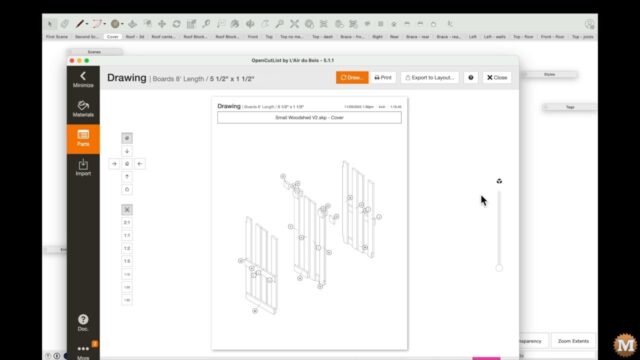
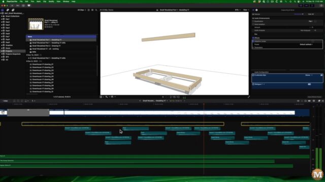
In this episode I’ll take that 3D model and create a fully dimensioned drawing from it. With all the views and details required to build it from standard nominal framing lumber. I’ll also make an automatic cut-list from a Sketchup plugin. In the next blog post I’ll use another plugin to create an animated sequence showing the shed being assembled. Also in that next post I’ll show you how I add sound effects for the animation using Final Cut Pro, the video editing software I use.
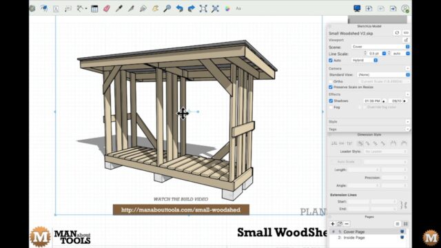
The Sketchup 3D Model and Scenes (Views)
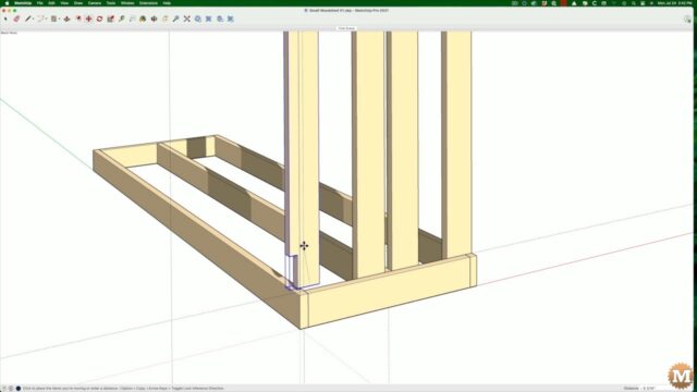
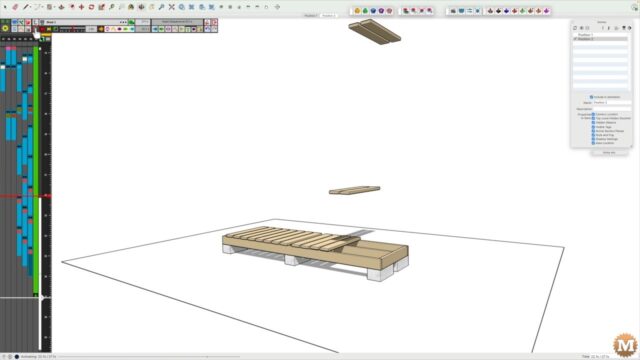
I’ll start in Sketchup with the completed model. I’ll need to create all the standard and detailed views before I can begin to add the dimensions. And I’ll also have to determine what I want to have visible in each of the views. And this is mainly controlled by the layers (or tags) that are visible or invisible. When building the model I tried to group objects and components into layers of similarity.
Overall Standard Views
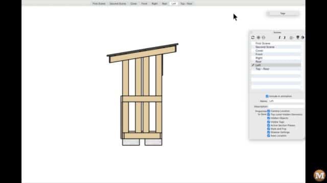
I’ll create some of the overall standard views like Top, Front, Right, Left, etc. And there’s icons for selecting these standard views at the top of the screen.
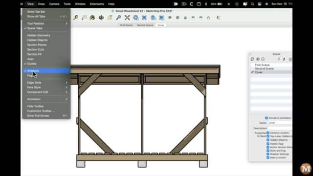
Scene (View) Settings
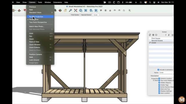
Then, I’ll change the camera view from perspective to orthographic. Then turn off the shadows. Then create a new scene with the plus sign. Scenes in the model will become views in the drawing. I can rename this scene to something that’s more descriptive than just Scene 4. I’ll call it Front.
(Disclaimer: As an Amazon Associate I earn from qualifying purchases. Thank you for helping to support my content this way. )
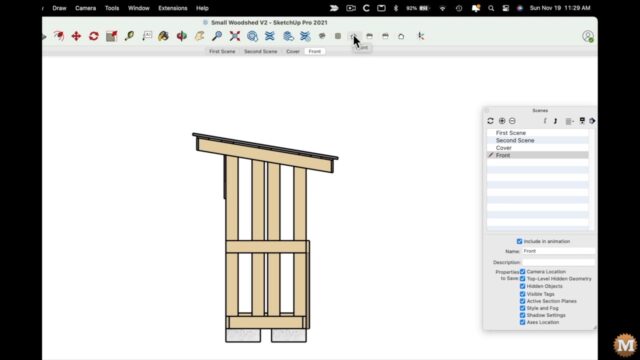
My orientation of the model when I built it was off by 90 degrees. So, I’ll just have to keep that in mind when I’m working here. Clicking the Front icon gives my models a Right side view. And that’s no problem as long as I stick with the current naming convention I’m using.
Making Scenes and Renaming
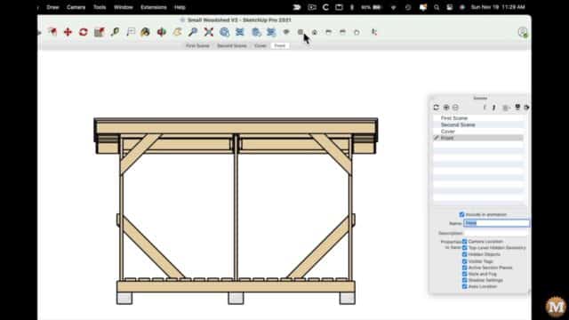
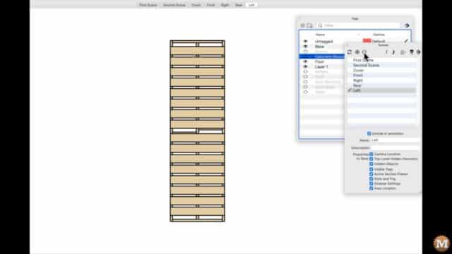
I’ll make a few more scenes and rename them. For this Top view I’ll deselect some of the visible layers to show just the floor and joists for this particular view. And I’ll call this Top – floor.
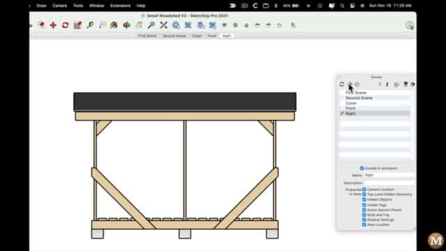
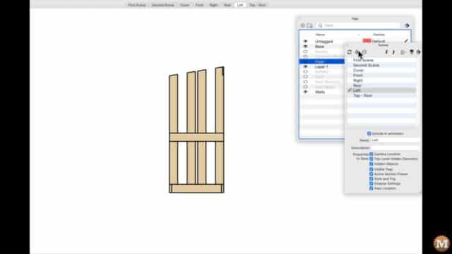
I’ll go back to my Left view and deselect some layers from that one. Then create a view and call it Left – walls.
And I can do the same for my first Top view. Deselect some layers and create a new scene and call it Top – joists.
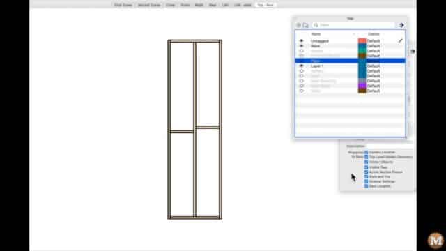
From the back of the shed, I’ll make some views of the floor and wall braces.
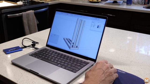
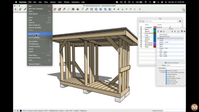
Send the Model to Sketchup
With those views done I have enough to start the drawing. I’ll now send that model from Sketchup to Layout. The program for assembling views and adding dimensions and detailed notes etc.
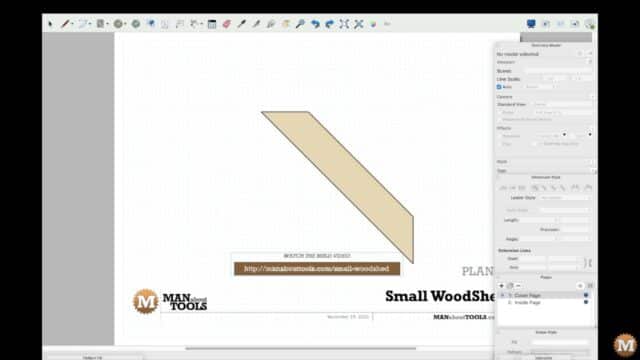
Layout asks me to select a drawing size and scale and/or a template. I’ll select my custom Man about Tools template I use for most of my drawings.
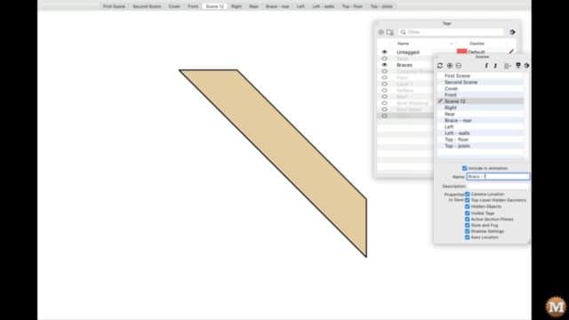
Then, I can set the drawing name and other details for this project. It automatically added the view of the corner brace. I can change that to the scene or view I created called Cover. And this is the image I want on the cover page of the drawing.